• Studio
  • Talks
  • bio
Lynne Yun Design
  • Studio
  • Talks
  • bio

Mechanical Clock

Inspired by a Ugears Clock, I’ve decided to embark on creating a mechanical clock.


Software:

  • For creating the gears necessary, I’m using Gear Generator. Here’s the specifics of the gear that I’m making.

Parts:

  • NEMA 14 Gear (SparkFun)

  • Worm Gear (Amazon)

Material:

  • 3mm thick clear acrylic panel

  • 5mm thick clear acrylic panel

  • 6mm acrylic rod

  • Weld On 3 adhesive

Gear Generator can simulate gears and let you create ‘child’ gears to parents and even has the gear-down ratio.

Gear Generator can simulate gears and let you create ‘child’ gears to parents and even has the gear-down ratio.


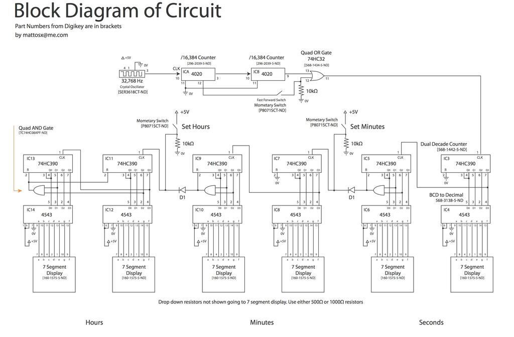
Schematics (as of Dec 3, 2019)

This is the approximation of the depth view. The gear columns will be made out of stacked acrylic pieces that are 4.5mm each, and thus is 45mm for the inside dimension. (approximate).

This is the approximation of the depth view. The gear columns will be made out of stacked acrylic pieces that are 4.5mm each, and thus is 45mm for the inside dimension. (approximate).

Here is the profile overview of the contraption and gear set. The colors note where the gears are in terms of the height (refer to the color chart above). The first gear (from the left) rotates once per minute, the big blue gear in the center marks …

Here is the profile overview of the contraption and gear set. The colors note where the gears are in terms of the height (refer to the color chart above). The first gear (from the left) rotates once per minute, the big blue gear in the center marks the minutes, and the last gear on the right marks the hours.


Process Documentation:

I cut a prototype with 3mm acrylic. Determined that I compensated too much for the laser kerf and the acrylic probably needs to be thicker. I was also using 5mm metal rods but this could also be acrylic to make everything more transparent. Also, the…

I cut a prototype with 3mm acrylic. Determined that I compensated too much for the laser kerf and the acrylic probably needs to be thicker. I was also using 5mm metal rods but this could also be acrylic to make everything more transparent. Also, the grey epoxy is a definite no. Also I thought I’d be able to put the motor in the back but this will make everything so much thicker.

As a solution for making the contraption thinner, I ordered worm gear parts. Need to redesign my box since the motor is now taking up horizontal space.

As a solution for making the contraption thinner, I ordered worm gear parts. Need to redesign my box since the motor is now taking up horizontal space.

Also, I might be sticking to metal rods for the first gear in case the metal component can wear down the acrylic rod.

Also, I might be sticking to metal rods for the first gear in case the metal component can wear down the acrylic rod.

Tuesday 12.03.19
Posted by Lynne Yun
 

Building Clock with CMOS

I’ve been trying to build a digital clock to show the 'generation’ of time, without the use of any devices that obscure how it functions.

While looking for a way to build a clock with a quartz crystal, I came across an Instructable that had a diagram of a clock built with CMOS chips.

Source: https://www.instructables.com/id/24-Hr-Digital-Clock-only-with-basic-CMOS-Chips/

Source: https://www.instructables.com/id/24-Hr-Digital-Clock-only-with-basic-CMOS-Chips/

However, the problem with this circuit was that the quartz crystal was a tiny chip that wouldn’t show it. So I decided to change the signal input into a diagram that I would understand. So found this schematic that was more straightforward in the way you could read how the signal is getting divided. I prototyped this first.

source: http://www.hackersbench.com/Projects/1Hz/

source: http://www.hackersbench.com/Projects/1Hz/

After I got that working, I started to build out a prototype. This process took the most time and a lot of tears :’-(

Simple explanation of clock

After making sure things worked and figuring out what each component does, I started to draw the form of the freeform circuit clock that I wanted to make.

drawn diagram
Diagram
Straightening spools of copper wire

Straightening spools of copper wire

Process shot of starting to build

Process shot of starting to build

Building process 1
Closeup

Finished clock!

Made a 💯 analog circuitry clock from a quartz crystal! There's ZERO software in here 😈 and the hardware is transparent. Don't be fooled by the usb cord, it only supplies the 5V power (via a phone charging block)! You can see the entire process and explanation by swiping through the photos.

145 Likes, 14 Comments - Lynne Yun (@lynneyun) on Instagram: "Made a 💯 analog circuitry clock from a quartz crystal! There's ZERO software in here 😈 and the..."

Wednesday 10.23.19
Posted by Lynne Yun
 

© 2022 Lynne Yun